 My Message
 Suggestions


Security and reliable real-time data flow are essential for internet of things (IoT). After seeing a lot of "this side of the press, where the lights will light up" like this kind of hardware, I and a friend wanted to do some obviously in the manipulation of it but almost no sense of the existence of data flow more interactive Something of something! So we decided to build a model that could control the "material" model, that is, imitate your hand movements and show the color on the basis of the finger positioning motion. Hope that with the help of this article, you can make your own hardware products.

The relevant source code about conceptual overview and some more in-depth understanding can be found in the PubNub blog, and the complete code can be found in GitHub library. The article "the LED matrix driver circuit" in Instructable introduces how the LED matrix the drive circuit is written in details.
Step 1: Parts and tools
There are a lot of ways to solve this problem, and some of the main ways are listed here.
Parts
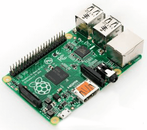
•Raspberry Pi V1 B +
•Jump motion controller
•5V power supply
•I2C PWM driver
•4 miniature servos
•4 miniature servo supporters
•LED and current limiting resistors
•Project Chassis
•Screws, bolts, nuts, paper clips
•Cable wrap - To keep the wire clean.
•Power outlets, switches, and cables
•Toggle switch --- Used to select the servo output mode
•Small button - Used as restart / shutdown button
•RGB LED + 2 & TImes; 470 ohm resistance - restart / shutdown indication
•Supports - To install a variety of parts
•Wires --- for connection.
Software and services
•PubNub - Data Stream Service. Free sandbox mode development.
•Java SE’s JDK8 - Be sure to get the correct version for your operating system.
•Jumping showcase and the Java SDK – Be sure to get the correct package for your operating system.
•PubNub Java SE SDK
•Java IDE - Choose your favorite, such as JGrasp, NetBeans IntelliJ, or Eclipse
•Project source code repository - hosted on GitHub
Raspberry Pi Building
•PubNub Python Library - This is a more in-depth guide to Raspberry Pi
•Internet connection - WiFi or Ethernet.
Tools
•Computer – Code and check Instructables
•Drill + Drill bit/ Driver - Drilling, Twist Screws, etc.
•Dremel rotary tool - for cutting holes in the chassis
•Hot glue gun
•Soldering iron + welding
•Laser cutting machine
•Screwdriver, pliers, etc
Step 2: Project Preview
Top-level design, divided into three main components:
1. Computer and jump motion controller ----- To publish data to the Internet.
2. Raspberry Pi in the "box" - subscribe to the data from the internet.
3. PubNub - The communication layer to connects these things securely.
The computer is very easy to handle, but it is more complex in the "box".
1. Raspberry Pi - the main controller with I2C bus communication
2. ATMEGA328P matrix drive circuit - through the I2C bus to receive commands, control 28 & TImes; 8 matrix RGB
3. Circuit based on TLC5916 LED - controlled by ATMEGA328P, sink LED matrix current
4. Adafruit PWM driver - through the I2C bus, driving 4 servos to receive commands
5. 5V, 5A power supply

First, we need to set the computer to use the jump motion controller.
Step 3: Java and Jump Motion Controller Settings

Java settings
We will use the Java SDK's jump motion controller, so we only need to install the Java development kit, which includes the Java operate environment. It is very simple that just choose the correct package for your operating system.
Instead of creating an installation package, it runs the source code directly from the Java IDE. This allows you to manipulate, modify and learn your own code. When you install the JDK, you need a good IDE, integrated development environment, like IntelliJ and NetBeans in Eclipse. Every user build different library, so you have to refer to the documentation to learn how to set up a new project.
Java source code
There is only one Java file that needs to run the code, but you must also install the jump motion and PubNub Java library. The GitHub's project library contains some necessary Java files.
Leap settings
Setting jumps is a bit tricky, and it will vary depending on the system, rather than being done step by step.
1. Download the SDK, and run the software and application in the jump motion.
2. Install the jump application, which will install all necessary drivers and processes.
3. Run the jump motion diagnostics visualization tool to ensure that the jump is working.
4. Read the Java SDK documentation, especially the setup.
PubNub settings
The last step is to download the PubNub Java SDK, which describes how to add a library to a Java project.
Step 4: Java source code
If you are not interested in Java code, you can skip this step; however, you should at least offer your personal PubNub key to code for it. The source code can be viewed on GitHub.
Here are some of the imports needed. If errors happen, it is likely that the SDK library is not properly installed.

It is vital to achieve Runnable of project and all jump activities work on their own threads. We first focus on project setting. Runnable interface and global variables initialization offer convenience later. The most important thing is the global variable "CHANNEL", and a pair of keys.

These strings are the only values that can be changed, and their channel names can retain the default "leap2pi" or some other alphas and numbers. It is necessary to use a unique name to prevent crosstalk between different projects.
Jump motion captures 300 frames per second. At every frame, we are able to get a lot of information, such as finger straightening, pitching, yawing and gestures. The value returned by the leaping pitch and yaw is radian, which is not helpful. We want to convert these valuesto the format accepted by the PWM driver. We first convert radians to degrees and then degrees between 150 and 600, which is equivalent to a servo. The acceptable servo PWM values for the typical operating range areexpressed by a 12-bit servo drive.
The basic formula in US is 2500 / (2 ^ 13-1) * (min. servo / max pulse width), so that [500, 2000] can map to [150,600].

The best way to make sure your code is working is to load the PubNub debug console. You can enter the channel name as publish and subscribe keys. Click on "Subscribe", when operate jump motion controller to run the Java code, the published data should be displayed in the message box.
Step 5: Install Raspberry Pi

With the operation of the Java code, it is time to set the Raspberry Pi dispatch data and use it to drive the LEDs and servos. In the already configured raspberry work with an internet connection, it can be WiFi or Ethernet, but this part needs you to finish! If you need help, you can find it on PubNub (someone wrote some time ago). In addition, you can use the monitor and keyboard directly on Pi to complete any one step, or use SSH remote login. Either way, but the ultimate goal of the project is to have a separate, no head, the installer will automatically run the required files to start.
The first step is to install the PubNub Python SDK.
Open the terminal and install the following:

It's very simple. Now we need to get a copy of all the files in the Pi directory of GitHub's repository. The easiest way to do this is to use Git clone to repurchase and then delete other unnecessary things:

The contents of the leap2pi directory should be the same as the files in the Pi directory of GitHub library. Finally, we want the Python script to start running. Here are two Python scripts to run:

It is so simple that we only need to edit a Linux system file as the root user. First, make sure the script is executable, and then open the rc.local file for editing.

You can use any of your favorite editors. The last line of the file should be "exit 0", which is to allow the use of the file clean export and terminal initialization. Here you can add any number of commands as long as they run the last "exit" command.
Insert the following, just above the "exit 0" command:

Save the file and exit. Pi will automatically run these scripts after starting up. The "&&" section ensures that every command runs. If you leave off, the bash terminal will always be loaded, so your personal information will be locked indefinitely.
Step 6: Connection between Raspberry Pi and servo drive

Raspberry Pi can drive the servo system directly, but it takes some effort. There is a dedicated PWM channel, but we need four wires. As a computer, Raspberry Pi is much better at the top level control than the low one.
It is easy to connect the Raspberry Pi. Pin 3 and 5 are found on the raspberry dispatched I2C line, but in this case it is also necessary to open the I2C communication channel and remember to view it. An important input pin is labeled "OE", ie the active-low "output enable" pin, when this pin remains low, the servo system is enabled, it can be connected directly to ground, or drive another One end IO pin. In this project, it is also from the ATMEGA328P matrix drive circuit also uses the I2C data line to connect to the R group.
In this figure, the servo is attached to the channel 1 PWM drive. In the project, set up such a steering gear like this:

Step 7: Close view on servo.py
It is easy to control servos with Python code as long as you understand Python. You can view this copy of the servo.py file on GitHub.
Like Java code, you need to publish your personal PubNub, where you subscribe to the key, and the name of the communication channel.
The Raspberry Pi will guide to do the following:
1. Reset the AVR matrix drive circuit.
2. Initialize PubNub with your key.
3. Subscribe to the PubNub channel "leap2pi".
4. Cycle down and check the output mode switch.
At the bottom of the system, all the work is done in the PubNub library. It will call all the operations and we only need to specify some callback.

The connection callback should be obvious. This function is actually doing things from the subscribe channel to receive messages. As described above, the box has a pair of output patterns selected for the slide switch connected to several IO lines.
•Mirror - The robot will reflect your movements; therefore, your left hand reverse control robot.
•Disabled - The servo system will stop responding.
•Clone - The robot will clone your movements; therefore, your left hand directly controls the left robot.
The only item worth noting in this file is to use GPIO pin 4 as the output. This pin drives the MOSFET to connect the gate of blue LED ground array.

Step 8: Close view on shutdown.py
Since Raspberry Pi is also used as a full-featured computer and should be properly shut down. It can cause drive failure, data loss and memory damage.
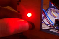
In order to solve this problem, I installed a simple button on the back of the box with an RGB LED. Press the button more than a second will turn to blue light, and Raspberry Pi will restart when the button is released. Press the button for a few seconds again will cause the LED to turn red and the signal will be turned off completely.
This feature is fully processed under the shutdown.py script. The following will occur in permanent cycle:
1.0.25 seconds sleep state
2. Check to press a button (low on pin)
3. Repeat forever
Step 9: Build the box
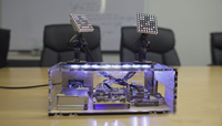
When building this box, we create a pair of vector files in Illustrator. These were sent to the laser cutting company (Ponoko), which gave us a bunch of laser cutting wood and acrylic. The fragments are still very large when they are sent back, making us have the joy of assembling them.
If you are careful, you can drill holes in acrylic (and wood) and install them with small screws. If you do not want to do this, you can arbitrarily build the box you want. But the supporter should be used to keep the circuit components securely mounted to the base, or to reduce some additional holes. Besides, install the power outlet, buttons and RGB lead on the back of the box.
The most important thing is the installation of the servo driller. When they are moving, the servo will cause fall or jump around of frame with light weight. Crucially, they were firmly installed on a sturdy surface, and we choose the cover of box.
Step 10: Complete
Some parts need to be customized, especially the actual box and servo supporter.


Mike
2/26/2017 6:54:18 PM
Remarkable.I have learned a lot from your post.